About
Kaden Adlington — Computer Engineering Student at the University of Canterbury. Avionics, embedded electronics and RF.
Christchurch, New Zealand
How I got here
I came into engineering through rockets. UC Aerospace's Level 1 programme was the first time I worked on a real vehicle instead of reading about one. I got to work on stability, aerodynamics, propulsion, and how sensors and a flight computer actually fit into an airframe. Level 2 was where I built airframes from scratch, laying up fibreglass and carbon fibre and fitting dual-stage recovery.
In 2023 I joined the Bluestone flight computer team and took on the sensing hardware. I led the design and selection of the sensor suite, including high-G accelerometers, magnetometers, barometric sensors, temperature and humidity sensors, and a thermocouple ADC interface over I2C. I laid out the Sensor Board schematic and PCB, keeping the I2C traces between the sensors and the RP2040 short. Bluestone tracked and returned telemetry on lower-powered test flights up to 8,000 feet.
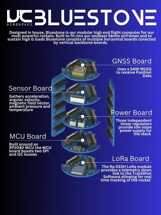
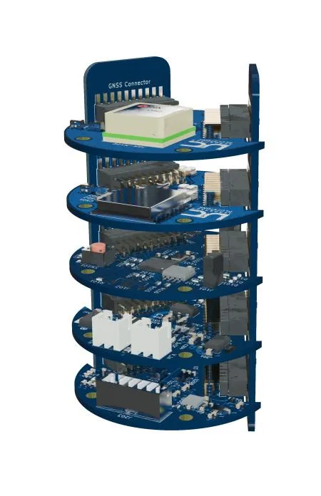
I took over as Avionics Team Lead in 2024 and led the second hardware revision of Bluestone. The first prototype had exposed a few problems: MCU USB interface faults, the move to USB-C, and a power stage that needed to be redesigned around more efficient switching regulators because of the thermal issues.
It also meant teaching. I organised and ran five hands-on electronics tutorials for UC Aerospace members with little prior electronics experience, covering component fundamentals, flight computer architecture, sensors, schematic design and PCB layout. I wrote the presentations, example PCBs and schematic templates that went with them. Members who completed all five sessions designed their own SMD flight computers from those examples, then assembled and tested them.
The same stretch produced a project that never got built. L1/L2 was to be a single-board flight computer for Level 1 and Level 2 rockets, built around an STM32WL with integrated LoRa alongside inertial, barometric and environmental sensing. The pyrotechnic channel was MOSFET-based, with several hardware safety stages ahead of it.
After discussing it with the wider team, we decided not to manufacture it. The scope was beyond the team's experience with safety-critical hardware, and the estimated manufacturing cost had come out significantly higher than expected. It taught me to be more realistic about what a team can actually validate and manufacture.
As Avionics and Tracking Lead through 2024–2025, I led the controller subsystem of UC Aerospace's LoRa launch control system. I designed the controller schematic, modelled the circuits, validated the hardware, and modelled the enclosure and mounting hardware in 3D CAD.
In the third-year electrical engineering design course, I was electrical systems lead on a LoRa range warning system built around a NUCLEO-WL55JC. I did the PCB layout and RF front end and integrated the firmware. The board took inputs up to 8S LiPo and produced regulated 12 V and 5 V rails.
In 2025 I became Huia Avionics Team and System Lead, covering the avionics architecture and flight systems of UC Aerospace's Huia programme. The stack was a Cube Orange+ running ArduPilot, RTK GNSS with a ground-based correction station, and long-range RF telemetry that was ground tested to approximately 20 km before flight operations.
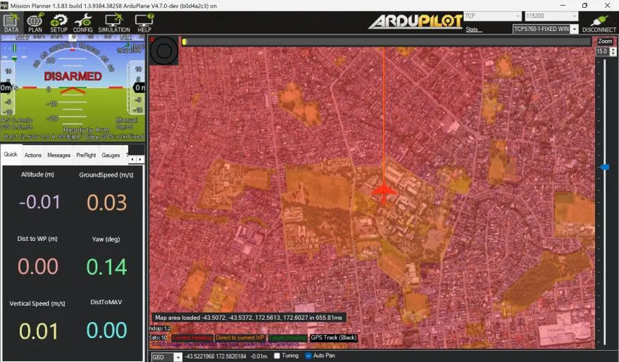
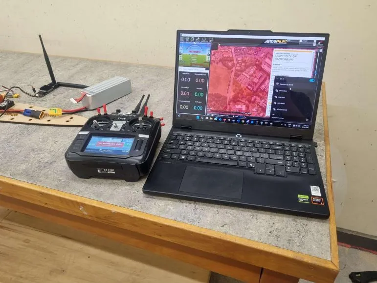
I deliberately kept the architecture modular rather than designing it just for the prototype. The 2026 programme ended up reusing it directly.
That 2026 programme is my final year project.
Huia is a fixed-wing electric ducted fan UAV built by a six-person Controls and Telemetry team and a six-person Structures team. I'm part of the Controls and Telemetry team, working on RF integration and overseeing the avionics.
The avionics work has covered everything from component selection through to physical integration and a custom ArduPlane 4.6.3 firmware build from source. I extended the firmware to carry ESC and battery temperatures over the existing telemetry link.
For the RF side, I ran an Ansys HFSS 2025 R2 study of two flexible-PCB antennas set at a 90° polarisation difference on a fibreglass fuselage. Isolation held above 47 dB through the 915 MHz band and above 43 dB across the full 800–1000 MHz sweep, against a 20 dB requirement.
I also modelled pack-level battery thermal runaway to size the containment, characterised ESC temperatures under airflow in the wind tunnel, and designed the electrical control system for the group's 5 m rail launcher.
Qube came directly out of that. Integrating commercial flight controllers on Huia meant dealing with the external modules they depend on, and I wanted to see what it would look like to build the flight computer itself.
Qube is a three-board flight computer I'm developing from ArduPilot's own source code and hardware definitions rather than starting from an existing reference design. It has a vibration-isolated sensor board, a flight-management board, and a carrier board holding the power architecture.
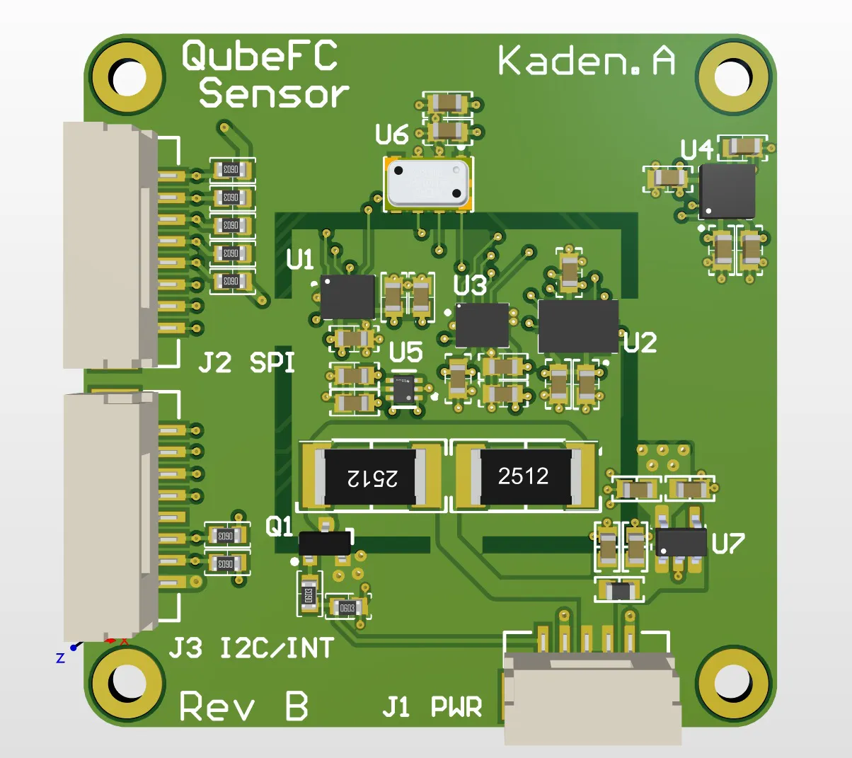
The sensor board is the furthest along. It's at Rev B in schematic and layout, but I haven't had it fabricated yet. The other two boards are still in schematic.
Skills
Self-assessed.
Hardware
- Electronics & PCB DesignAdvanced
- Power SystemsAdvanced
- SPICE SimulationIntermediate
- Avionics & Flight SystemsAdvanced
- Mechanical & CAD IntegrationAdvanced
- RF & Antenna SimulationBeginner
- Thermal & Failure-Mode ModellingBeginner
Firmware
- Embedded Systems & FirmwareAdvanced
Software & delivery
- Software DevelopmentAdvanced
- Computer Vision & Signal ProcessingIntermediate
- System Integration & TestingAdvanced
- Leadership & MentorshipAdvanced
Tools
Everything below has been used on a project in this portfolio.
EDA and CAD
Simulation
Flight stack
Silicon
Languages
Roles
- 2026
Team member, RF integration and avionics
Huia EDF UAV — final year project
- 2025–2026
General Executive
UC Aerospace
- 2025
Huia Avionics Team and System Lead
UC Aerospace's Huia programme
- 2024–2025
Avionics and Tracking Lead
UC Aerospace — Bluestone flight computer, the LoRa launch control system, and the electronics tutorial series
- 2023–present
UC Aerospace member
Rocketry programme — Level 1 and Level 2
- 2023–2025
Technical Intern
UCE Makerspace, Centre for Entrepreneurship — additive manufacturing support and inductions, CAD in SolidWorks and Fusion 360, and electrical design assistance
- 2023
Bluestone team member
UC Aerospace — Bluestone flight computer
Education
- 2022–present
University of Canterbury
BE(Hons) Computer Engineering. Final-year.
- 2017–2021
Mount Maunganui College
NCEA Levels 1 to 3, all endorsed with Excellence.
Based in Christchurch, NZ. Outside university: High-powered rocketry, Scouts New Zealand and RC aircraft. The fastest way to reach me is email.