Final-year Computer Engineering student focused on avionics, embedded electronics, and RF systems. I've led the design of flight computers and telemetry systems for high-powered rockets and experimental aircraft, building hardware engineered to perform reliably under high-G, high-vibration, and extreme environmental conditions, with current work spanning a custom flight controller and an RF optimisation project for a composite UAV airframe.
2026 · Team member - RF integration; oversaw avionics integration
Huia is a fixed-wing electric ducted fan UAV, my final-year capstone, built by two six-person teams: Controls and Telemetry, and Structures. I designed and integrated the aircraft's avionics around ArduPilot — flight computer, GPS, power sensing, telemetry, video and RC — and built the custom ArduPlane firmware that ties them together. Alongside that I ran the RF and antenna placement study in Ansys HFSS, with further work on battery thermal-runaway containment, ESC thermal characterisation and the launcher's electrical control system.
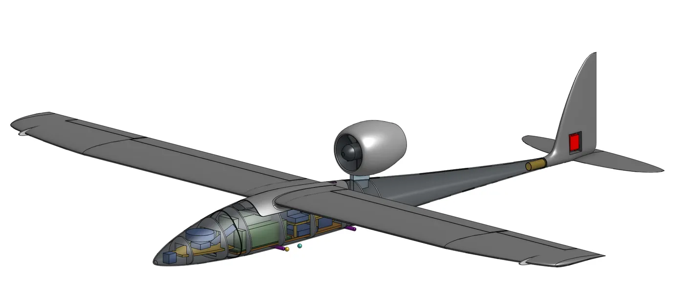
1Forward Avionics Bay
The forward bay houses the FPV camera system, telemetry antenna 1, and GNSS unit. A sliding hatch provides access for removal and maintenance, while the fibreglass construction keeps the bay transparent to RF signals.
2Battery Block
The propulsion pack is a GNB HV 8S2P 9000 mAh, 274 Wh battery. A full thermal-runaway model estimated 1.97 MJ of released energy, 108 to 144 L of vent gas, and peak temperatures of 1340 to 1440 °C. A 13 mm ceramic liner keeps the enclosure’s inner surface near 237 °C, compared with roughly 813 °C for uninsulated fibreglass.
3Aft Equipment Bay
The fuselage is constructed entirely from fibreglass, which is transparent at the 915 MHz telemetry frequency and allows the antennas to be mounted internally without RF windows. Conductive components inside the fuselage, including aluminium supports, control rods, wiring, and avionics, can still affect antenna performance. I modelled these structures in Ansys HFSS to assess their effect on radiation patterns and isolation. Two RFDFLEX2 antennas were positioned at opposing locations with a 90° polarisation difference, achieving over 47 dB isolation across the 915 MHz band and over 43 dB across 800–1000 MHz, against a 20 dB requirement.
4Ducted Fan Pod
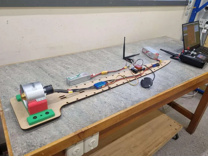
The fan is driven by an ESC enclosed within the airframe with minimal airflow, which initially resulted in higher-than-expected temperatures. Wind-tunnel testing under load recorded upper sensor temperatures of about 85 °C at 0 m/s, 62 °C at 10 m/s, and 33 °C at 40 m/s. The main constraint was heat accumulation rather than steady-state temperature, and the short flight duration means passive cooling is sufficient.
Cutaway:Huia airframe, fuselage opened along the lower left, ducted fan pod on its pylon above and behind the wing.
Ten more projects in avionics, embedded electronics and RF, flight computers, telemetry, simulation and test tooling. Each one carries the figures and the numbers behind it.
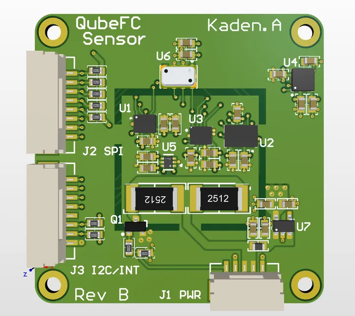
A custom three-board flight computer designed to run ArduPilot on a high-performance microcontroller, separating the vibration-sensitive sensor electronics from the main flight computer and power distribution hardware. The sensor board is the first completed hardware component; the flight-management and carrier boards are currently in the schematic development phase.
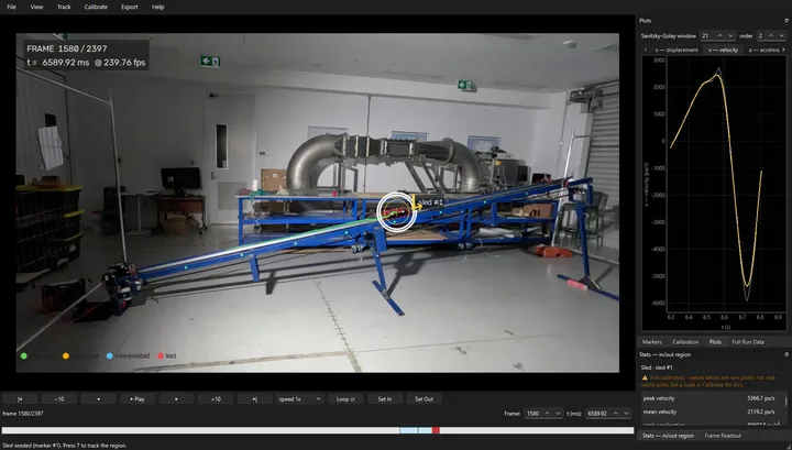
A computer vision system that measures sled position, velocity, and acceleration during launch testing using only camera footage. A markerless, colour-based tracking pipeline replaced the original marker-based tracker, working from standard 30 fps recordings through to high-speed footage exceeding 1000 fps.
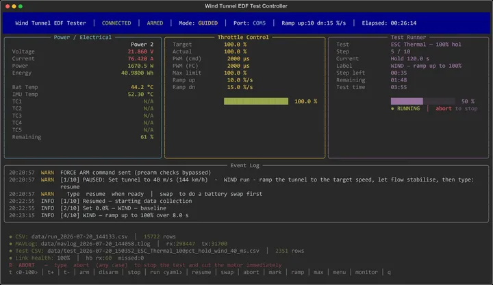
A Python terminal application that automates flight hardware characterisation testing, using a Cube Orange+ flight controller as both a control interface and data-acquisition platform. Test procedures are defined in YAML, safety limits are enforced within the hardware communication layer, and a simulation mode with an automated pytest suite allows validation without physical hardware.
The avionics architecture for UC Aerospace's Huia, a multi-year project developing a high-performance fixed-wing UAV platform. It was built around a Cube Orange+ running ArduPilot, RTK-capable GNSS with a ground-based correction system, and long-range RF telemetry ground tested to approximately 20 km. The stack was integrated and validated on an electric proof-of-concept aircraft, with a commercial off-the-shelf airframe used as a separate autopilot test platform.
avionicsrftest
2023–2024 · Team member 2023; Avionics Team Lead 2024
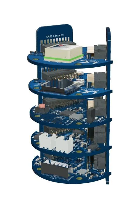
A flight computer developed over two hardware revisions and two roles. As a team member in 2023 I led the sensor suite design and laid out the Sensor Board; as Avionics Team Lead in 2024 I directed the second revision, addressing the USB interface faults and thermal issues the first prototype exposed. The system provided reliable tracking and telemetry on lower-powered test flights up to 8,000 feet.
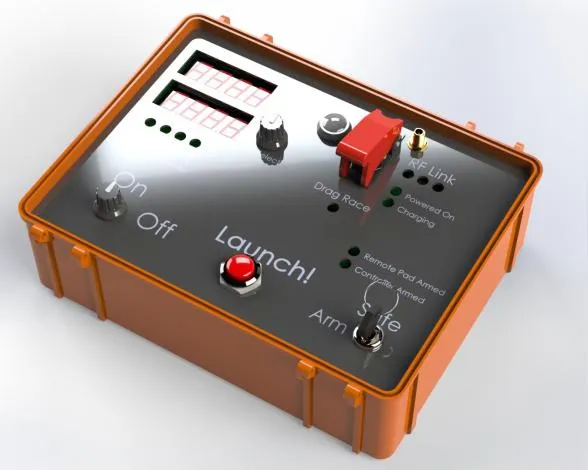
A battery-powered launch controller talking to pad hardware over LoRa. It runs on dual 18650 lithium-ion cells with integrated USB-C charging, and its panel carries two seven-segment displays, status indicators and a launch button. The button interface is debounced in hardware using RC filters and Schmitt triggers rather than in firmware. I did the schematic design, circuit modelling and hardware validation of the controller board, and modelled the enclosure and mounting hardware in 3D CAD.
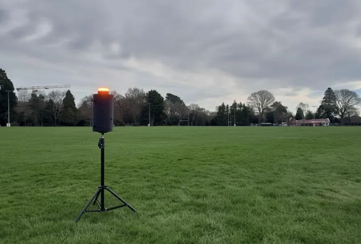
A tripod-mounted field unit carrying siren and beacon alerts across a high-power rocketry range. I led the electrical design and implementation, covering PCB layout, RF front-end development and firmware integration around a NUCLEO-WL55JC and its STM32WL, with the LoRa stack configured half-duplex for bidirectional exchange between the launch site and range safety stations. The custom PCB runs from inputs up to 8S LiPo, generates regulated 12 V and 5 V rails, and switches the unit's siren and beacon.
Five structured workshops taking UC Aerospace members from datasheets and component packages through flight computer architecture, sensor selection, schematic practice and PCB layout. Participants who completed all sessions assembled and tested their own SMD-based flight computers.
pcbavionics
Earliest UC Aerospace rocketry work · UC Aerospace member
My first real introduction to rocket design, flight dynamics and avionics, working with actual rockets rather than the theory of them. Design covered aerodynamics, stability and propulsion; the avionics side was an introduction to integrating sensors and flight computers. The grounding it gave me is what the more advanced rocketry and embedded systems projects here were built on.
Higher-performance rockets designed and built from scratch, which brought in flight simulation, dual-stage recovery and composite construction. I laid up fibreglass and carbon-fibre airframes, working through material selection, layering technique and structural assembly, and integrated avionics and dual-stage parachute recovery into the rockets.
rocketryavionics
Roles
Experience and education
2025–2026
UC Aerospace
General Executive
2024–2025
UC Aerospace
Avionics and Tracking Team Lead
2023–2025
UCE Makerspace, University of Canterbury
Technical Intern — additive manufacturing, CAD and electrical design support