- Role
- Avionics Team and System Lead — flight computer, power, communications and sensor integration
- Timeframe
- 2025
As Avionics and Systems Lead, I was responsible for developing the avionics architecture and flight systems for UC Aerospace’s Huia programme, a multi-year project focused on developing a high-performance fixed-wing UAV platform. The initial objective was not the final aircraft. It was a reliable avionics foundation that could be validated on smaller aircraft before being integrated into future high-performance airframes.
The project began in early 2025 with the development of an electric-powered proof-of-concept aircraft, providing a platform for validating flight control, telemetry, power systems, and sensor integration before transitioning to a larger and more demanding airframe. Alongside the custom aircraft development, a commercial off-the-shelf fixed-wing aircraft was used as a dedicated avionics test platform, allowing autopilot systems to be tested and iterated rapidly without requiring changes to the primary airframe.
During this phase I led the avionics system design: flight computer selection, power architecture, communication systems, and sensor integration planning. The decision that shaped the rest of the work was to design a modular, scalable architecture that could support future aircraft development rather than a one-off prototype.
The avionics stack consisted of a Cube Orange+ flight controller running ArduPilot, a high-accuracy GNSS system with RTK capability, a ground-based RTK correction system, and long-range RF telemetry, giving autonomous flight capability, precision positioning, and reliable communication between the aircraft and ground station. The telemetry system was ground tested to approximately 20 km, validating the communication link prior to flight operations.
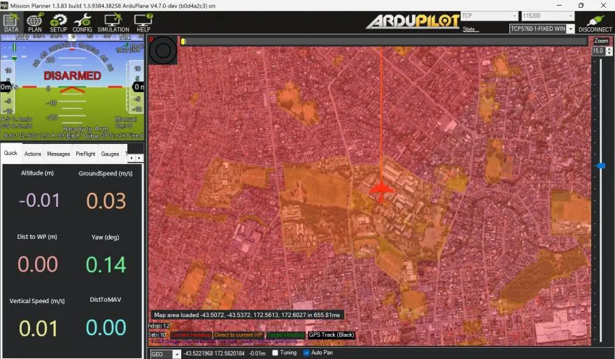
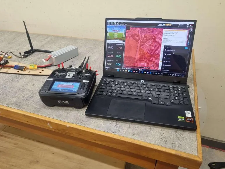
The avionics system was integrated into the electric test aircraft and validated through ground testing, simulation, and flight preparation workflows using Mission Planner, verifying sensor operation, telemetry reliability, flight computer configuration, and command responsiveness before progressing toward more advanced aircraft platforms.
The project also established the communication and integration approach used in later Huia development. A distributed avionics architecture using interfaces such as CAN was investigated to support future expansion of sensors and payload systems while reducing wiring complexity and improving reliability in electrically noisy aircraft environments.
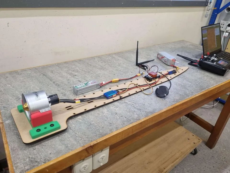
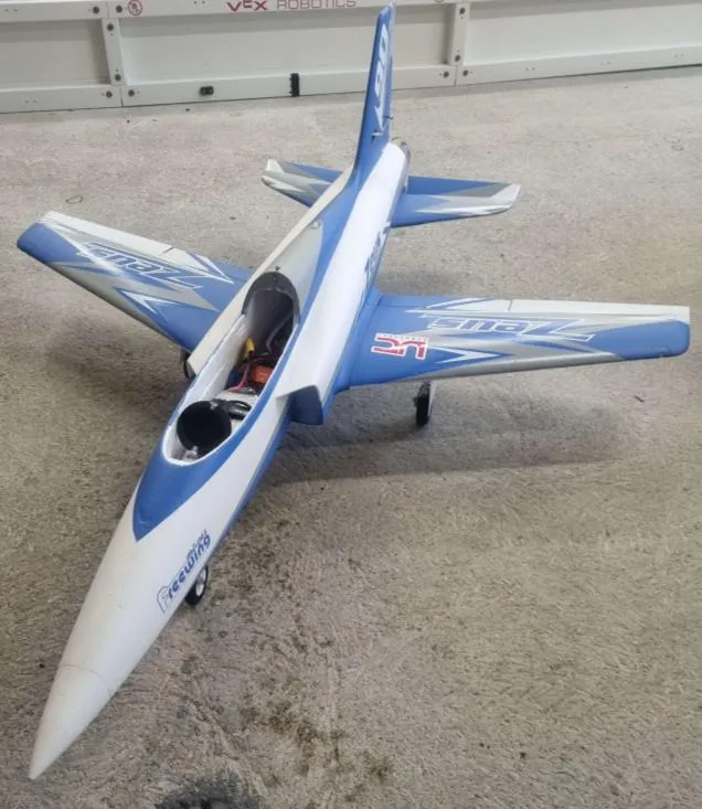
Beyond the hardware integration, I developed the initial flight-testing approach, including validation procedures, safety checks, and performance benchmarks to guide future flight campaigns. The avionics foundation developed during this phase became the basis for later Huia aircraft iterations, including advanced telemetry, RF optimisation, custom avionics development, and higher-performance flight systems.
Choosing a modular, scalable avionics architecture rather than optimising narrowly for the electric prototype meant this work didn’t end when the prototype’s flight testing did. The 2026 Huia EDF UAV programme reused it directly instead of starting the avionics design over from nothing.
Technologies
Key outcomes
Independently designed and validated the avionics and CAN communication architecture for UC Aerospace’s experimental aircraft. Achieved reliable 20 km telemetry range during ground testing, successful system integration on the electric prototype, and developed a structured flight test plan forming the foundation for the 2026 Huia EDF UAV programme.