- Role
- Solo project
- Timeframe
- April 2026
The inspiration for Qube came from my work on Huia, where I spent much of my time integrating commercial flight control hardware into the aircraft. While commercial flight controllers provide a mature and reliable platform, they rely on numerous external modules for functions such as power monitoring, airspeed sensing, GPS, telemetry, and other peripherals.
As additional capability is added, the avionics quickly become a collection of interconnected boards, increasing wiring complexity, packaging constraints, and integration effort. They are also designed primarily for the wider UAV and hobby market, meaning there is limited opportunity to develop custom hardware solutions tailored specifically for the requirements of a high-performance fixed-wing aircraft.
At the same time, my advanced embedded systems courses introduced concepts such as communication buses, power electronics, PCB design, and embedded hardware architecture that I wanted to apply to a practical aerospace project. Qube became an opportunity to combine those concepts with the practical avionics experience gained through Huia by designing a complete flight computer from first principles.
Qube is a custom three-board flight computer designed to run ArduPilot on a high-performance microcontroller. The architecture follows the modular approach used by modern autopilot systems, separating the vibration-sensitive sensor electronics from the main flight computer and power distribution hardware. The system consists of a dedicated sensor board, a flight-management board containing the main processor and I/O controller, and a carrier board responsible for power management and external connectivity.
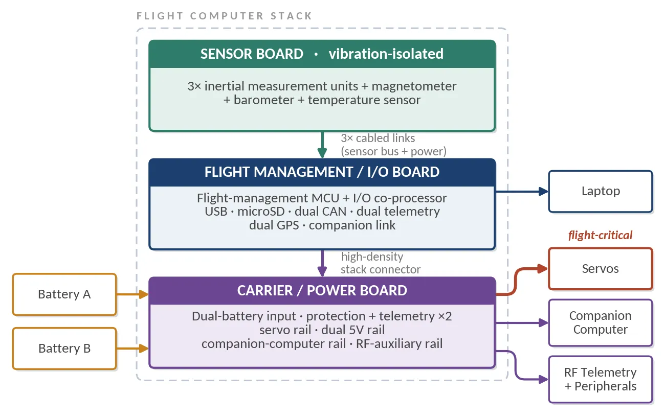
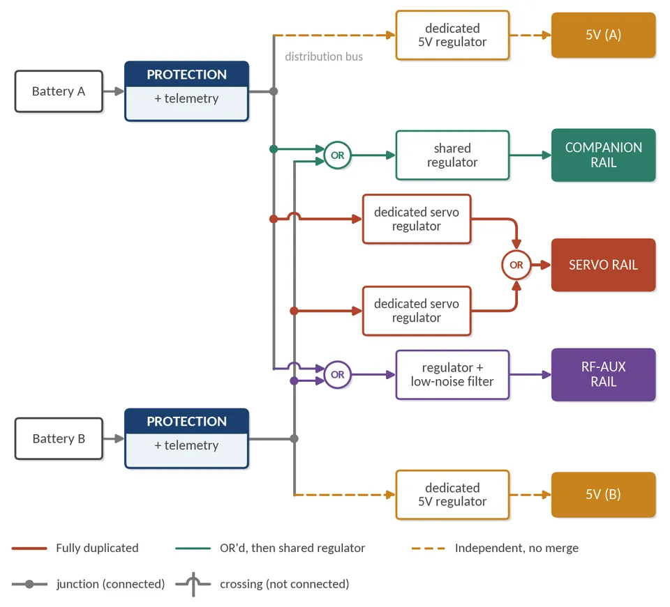
The hardware architecture was developed from the ArduPilot source code, hardware definitions, and component documentation rather than copying an existing reference design. Key hardware choices were based around components already proven within the ArduPilot ecosystem, leveraging years of community testing and optimisation while allowing the surrounding electronics to be tailored to the requirements of this aircraft. A major design goal was applying redundancy where it meaningfully improves flight reliability while avoiding unnecessary complexity. Each subsystem was evaluated based on the consequences of failure, with critical functions receiving additional protection or backup paths while lower-risk systems remained intentionally simple.
The sensor board is the first completed hardware component of Qube and contains a redundant navigation suite consisting of multiple inertial sensors, a magnetometer, barometer, and temperature monitoring. Multiple IMUs allow the flight software to compare and combine measurements, improving reliability while detecting sensor faults before they affect flight performance. The sensors are located on a dedicated board that can be mechanically isolated from aircraft vibration, improving measurement quality. An integrated heater maintains a more stable operating temperature, reducing thermal bias drift and improving measurement consistency.
The remaining flight-management and carrier boards are currently in the schematic development phase. The flight-management board separates high-level flight processing from safety-critical hardware interfaces, with the main processor responsible for sensor fusion, navigation, and control while a dedicated I/O controller manages interfaces such as RC input, servo outputs, and safety functions. The carrier board implements the power architecture, including redundant battery inputs, monitoring, protection, and regulation.
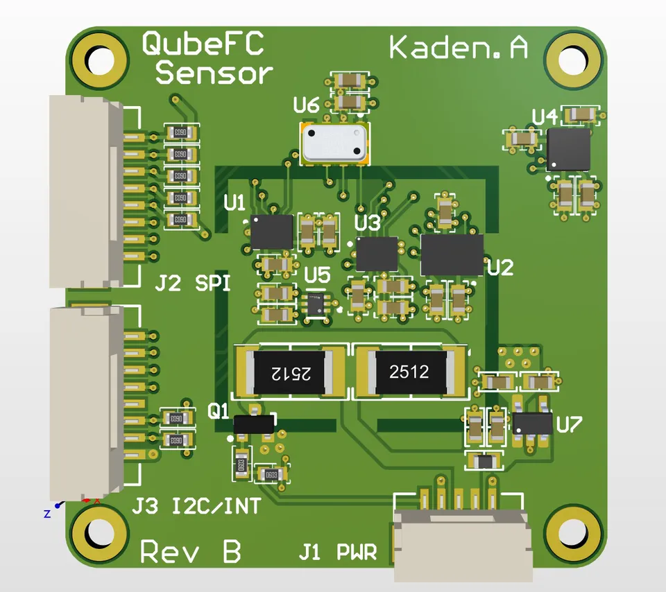
The sensor board below is the same hardware as Figure 20, exported from the CAD and tessellated for the browser. The board is 40 mm square; the two board-to-board connectors on one edge carry the sensor bus and power up to the flight-management board.
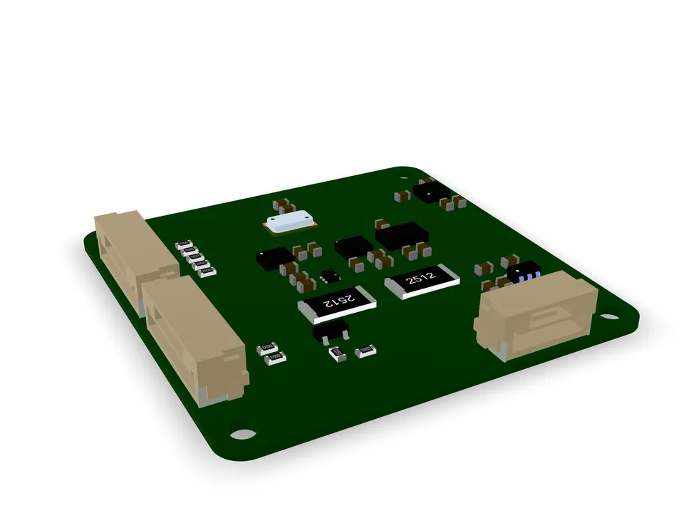
Drag · Ctrl-scroll to zoom
A significant challenge throughout the hardware development process was navigating the global semiconductor shortage. Component availability became a key design constraint, requiring alternative parts to be evaluated, hardware designs to remain flexible, and components to be sourced across multiple suppliers. This required developing a stronger understanding of designing around availability constraints rather than selecting ideal components first and assuming they would always be obtainable. Managing these constraints became an important part of the engineering process and influenced decisions around component selection, footprints, and supply-chain resilience.
The design integrates the communication interfaces required for a modern autonomous aircraft, including CAN, SPI, I2C, UART, USB, and PWM. CAN was a particular focus, allowing me to move beyond simply using existing avionics hardware and instead design the electrical interfaces, bus topology, and supporting hardware required for a distributed avionics system.
Qube combines embedded systems design, PCB development, power architecture, sensor integration, communication interfaces, and avionics system design into a complete flight computer platform. The project has also provided practical experience in hardware validation and design verification, including using simulation tools such as Ansys IcePak to evaluate thermal performance and power dissipation before hardware manufacture.
Technologies
Key outcomes
Designed a three-board ArduPilot-compatible flight computer architecture consisting of a vibration-isolated sensor board, flight-management board, and carrier/power board. The design focuses on modularity, selective redundancy, and integration of aerospace communication interfaces. The project was shaped by two key challenges: determining where redundancy meaningfully improves reliability and adapting hardware design around component availability during the global semiconductor shortage.