- Role
- Team member - RF integration; oversaw avionics integration
- Team
- Two six-person teams - Controls & Telemetry, Structures
- Timeframe
- 2026
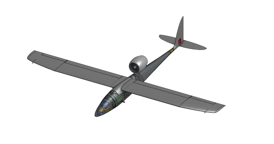
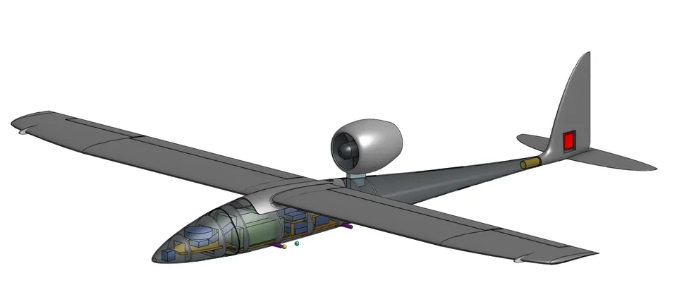
My Final Year Project centres on Huia, a fixed-wing electric ducted fan (EDF) UAV developed as my final-year capstone project, continuing directly from research and testing done throughout 2025. The aircraft was developed by two teams: a six-person Controls and Telemetry team responsible for avionics, communications, and flight systems, and a six-person Structures team responsible for airframe design and integration.
My primary role has been designing and integrating the aircraft’s avionics around ArduPilot. This meant selecting the flight computer, GPS, power-sensing, telemetry, video, and RC components, then working out how they all fit together as a single system. I carried out the physical integration and built the custom flight firmware that ties everything together. Alongside that, I took on the RF and antenna placement study using Ansys HFSS to simulate the aircraft’s electromagnetic performance and validate the telemetry architecture. I also contributed to battery thermal-runaway analysis and containment design, ESC thermal characterisation under airflow, and the electrical design of the remotely operated launch system.
The avionics integration and RF work below are both my individual project components. The battery containment analysis, ESC testing, and launch system electronics were also work I led personally, done alongside teammates leading structures, propulsion sizing, and flight controls.
I also developed supporting software tools for the project: automated flight-hardware test tooling using pymavlink, and computer-vision software for analysing high-speed launch-system footage and comparing measured performance against simulated results.
1.0
Avionics integration & custom firmware
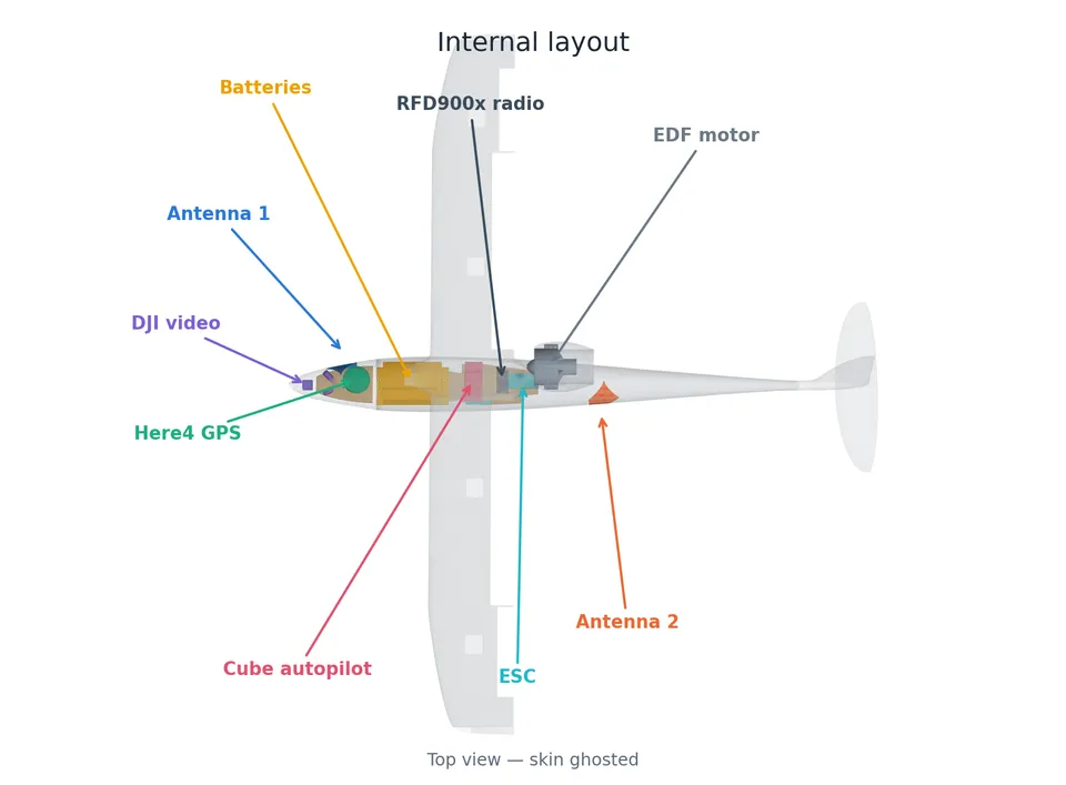
A major part of my contribution to Huia was integrating the aircraft’s avionics into a complete autonomous flight system built around ArduPilot. This extended well beyond selecting individual components. It involved designing the power distribution, communication architecture, wiring, and physical installation so that the flight controller, GPS, telemetry, radio control, video system, and supporting sensors all operated as a single, reliable system.
The avionics architecture was developed to be modular and scalable, allowing systems validated on the earlier electric prototype to transition directly into the current aircraft. Communication interfaces, power requirements, and mounting arrangements were all considered together to simplify integration, improve reliability, and support future expansion of the platform.
Alongside the hardware integration, I developed a custom ArduPlane 4.6.3 firmware build from source. Rather than relying on the standard pre-built firmware, this allowed only the functionality required by the aircraft to be included, reducing flash usage while providing a reproducible configuration tailored to the final hardware. The firmware was also extended to support additional thermocouple sensing for in-flight ESC and battery temperature monitoring, allowing thermal data to be transmitted through the existing ArduPilot telemetry system without requiring separate logging hardware.
Together, the avionics integration and firmware work established the aircraft’s flight control platform that the RF optimisation, thermal testing, and automated hardware testing work was all built on top of.
Technologies
Key outcomes
Integrated the flight computer, GPS, telemetry, video, and RC systems into a complete avionics architecture for Huia, while developing a custom ArduPlane firmware build from source. Extended the system to support ESC and battery temperature monitoring through the existing telemetry pipeline, allowing the Controls and Telemetry team to continue hardware and software validation as the airframe evolved.
2.0
RF & antenna placement
I oversaw telemetry and communications for Huia, responsible for reliable long-range communication between the aircraft and ground station. A key challenge was maintaining telemetry performance during manoeuvres, since airframe materials and internal structures can block, reflect, or distort antenna radiation patterns and potentially cause link loss during critical flight conditions.
After iterative discussions with the Structures team, we decided early on to move to an all-fibreglass fuselage rather than carbon fibre, since it was the more logical choice for both antenna performance and structural design. Carbon fibre would have needed dedicated RF windows cut into the fuselage to let signals through, since it’s electrically conductive. A non-conductive skin removes that shielding problem, though internal conductive components such as aluminium supports, control rods, wiring, and avionics still need to be accounted for in the antenna design.
I investigated antenna placement and polarisation diversity to improve telemetry reliability throughout the aircraft’s flight envelope. Optimising the position of a single antenna can improve performance in one direction, but it cannot eliminate coverage nulls created by the aircraft’s structure or changes in attitude. Using two antennas mounted at different locations and with different polarisations produces complementary radiation patterns, so areas of reduced coverage from one antenna are typically covered by the other. This approach provides more consistent telemetry performance across all flight attitudes and significantly reduces the risk of link loss during manoeuvres.
Using Ansys Electronics Desktop (HFSS) 2025 R2, I modelled the fibreglass fuselage, its internal conductive structures, and two RFDFLEX2 flexible-PCB antennas, positioned with a 90 degree polarisation difference at opposing locations on the airframe. Simulations were run across 800-1000 MHz around the 915 MHz telemetry band.
Simulated antenna performance (installed on airframe)
| Parameter | Sym | Req. | Result | Unit | Conditions |
|---|---|---|---|---|---|
| Return loss @ 915 MHz, antenna 1 | S11 | — | -11.8 | dB | Installed |
| Return loss @ 915 MHz, antenna 2 | S22 | — | -15.0 | dB | Installed |
| Power accepted @ 915 MHz, antenna 1 | — | 93% | Installed | ||
| Power accepted @ 915 MHz, antenna 2 | — | 97% | Installed | ||
| Return loss range, antenna 1 | S11 | — | -11.8 to -15.2 | dB | 900-930 MHz band |
| Return loss range, antenna 2 | S22 | — | -15.0 to -18.5 | dB | 900-930 MHz band |
Simulations show both antennas achieve efficient coupling across the operating band. Antenna 1, positioned at the front-right of the fuselage and wrapped at 51 degrees, achieves -11.8 dB return loss at 915 MHz. Antenna 2, positioned at the rear-left and wrapped at 50 degrees, performs at -15.0 dB. The installed configuration accounts for proximity effects and internal conductive structures within the fuselage.
The fibreglass fuselage produces a frequency shift of approximately -3.3% in both antennas, reflecting the consistent electromagnetic environment across different mounting locations. This detuning is a property of the blade-over-GFRP configuration itself rather than localized effects, demonstrating predictable behaviour across the airframe. Both antennas remain well-coupled across the operating band despite this shift.
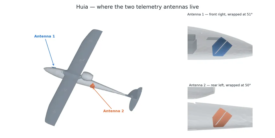
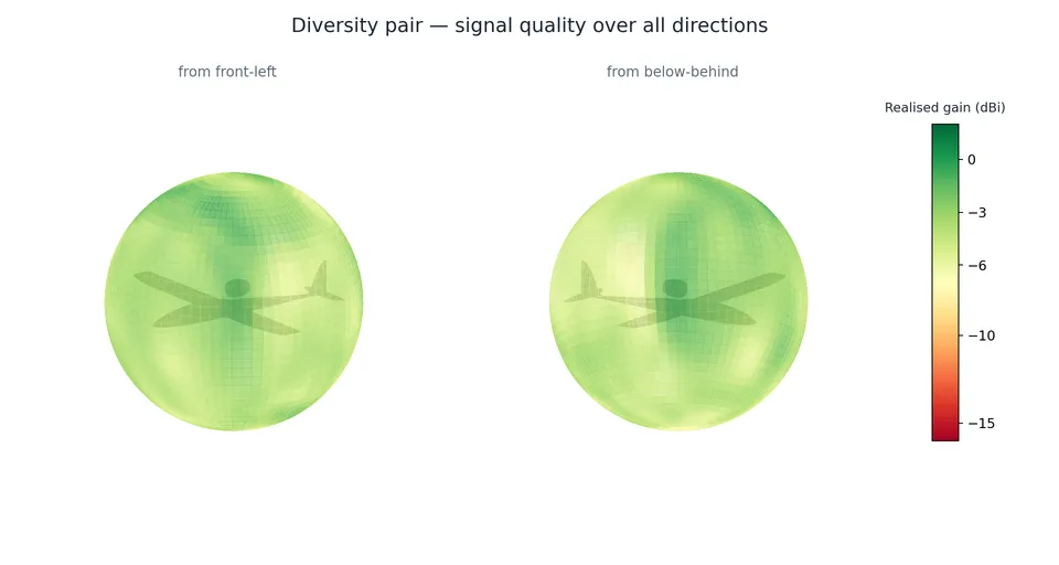
The two antennas are positioned as a diversity pair with spatial and polarisation separation. Antenna 1 (front-right, 51 degree wrap) and Antenna 2 (rear-left, 50 degree wrap) create complementary coverage across the aircraft’s flight envelope. The 3D radiation patterns show each antenna’s weaker regions covered by the other, providing consistent link margin during manoeuvres.
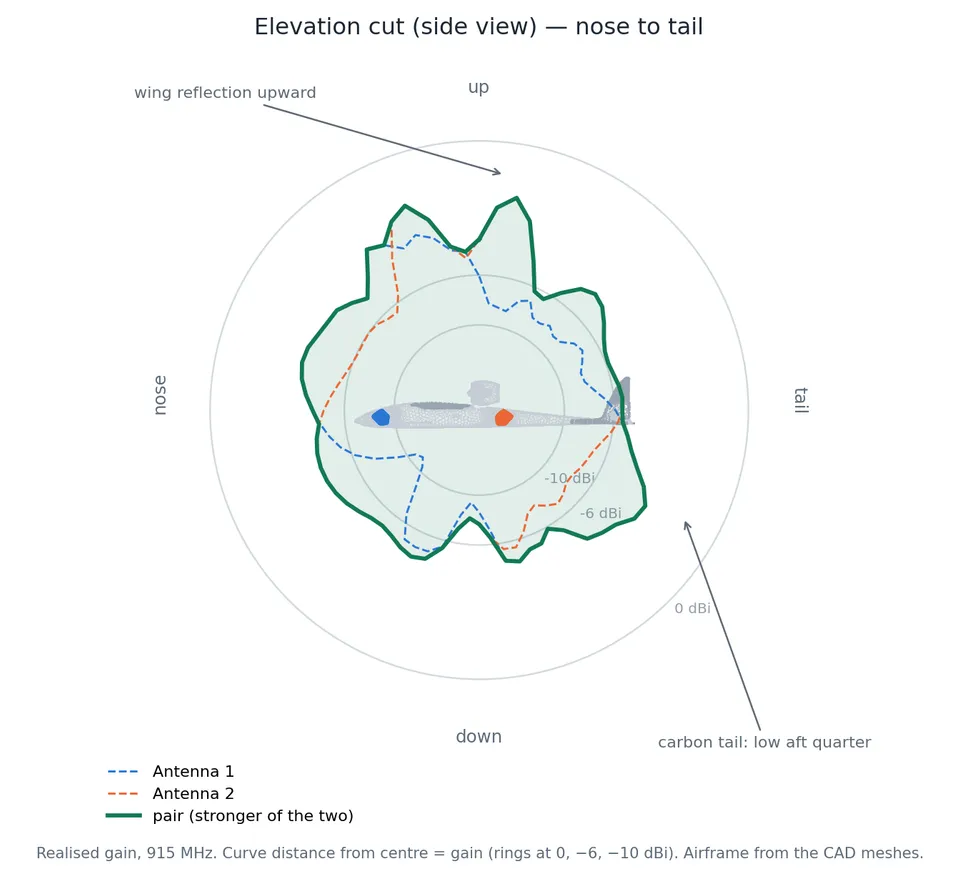
Simulated azimuth coverage demonstrates near-omnidirectional performance in the horizontal plane, with the diversity pair maintaining coverage even in aircraft attitudes that would create deep nulls with a single antenna. Elevation patterns show the expected lobing characteristic of the flexible-PCB antenna elements, with the airframe integration contributing to the overall coverage pattern rather than degrading it.
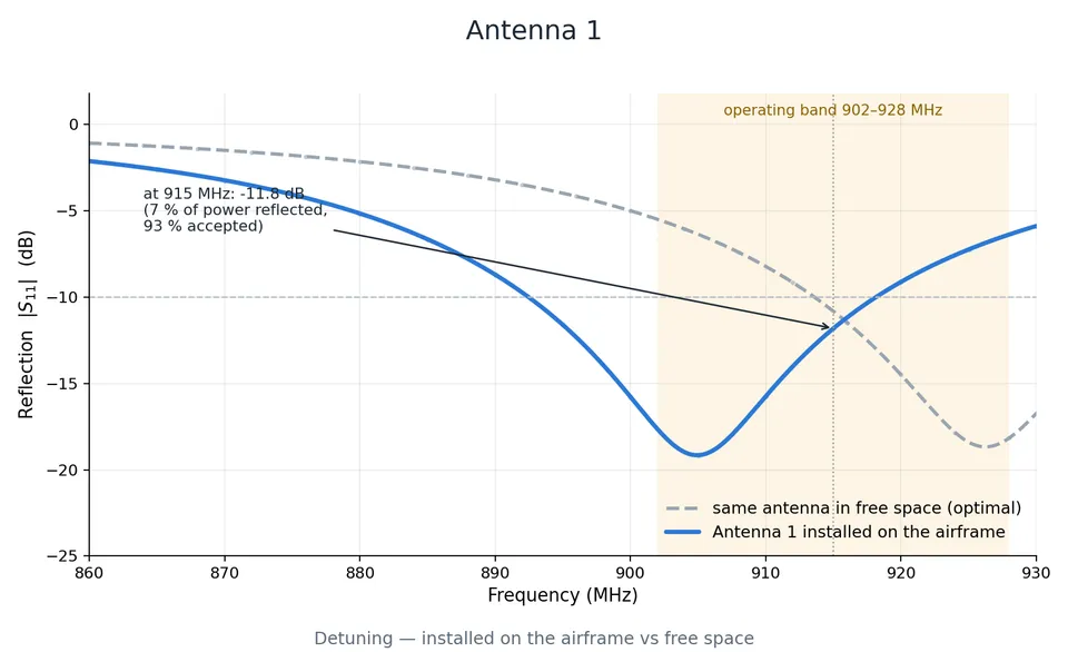
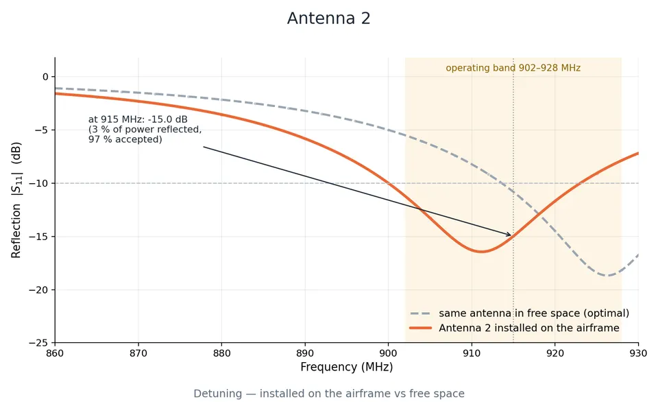
The installed antennas show frequency shifts relative to free-space response due to electromagnetic coupling with the fibreglass fuselage and internal structures. Antenna 1 shifts toward higher frequencies with some bandwidth narrowing, while Antenna 2 exhibits more stable performance across frequency. Despite these shifts, both antennas maintain strong coupling (greater than 93% power acceptance) throughout the operating band.
The consistent -3.3% shift across both antennas, despite different mounting locations and local air gaps, indicates that antenna detuning is dominated by the fundamental blade-over-GFRP configuration rather than by localized geometry variations. This predictability was a key finding that validated the placement strategy and the choice of fibreglass construction.
The diversity pair achieves approximately -30 dB inter-antenna isolation, ensuring that fading in one antenna’s signal is largely independent of the other. Combined with the 90 degree polarisation difference, this isolation maximizes the benefit of spatial diversity for reception quality.
Radiation pattern analysis shows approximately 7 dB of null-fill from the diversity pair. Areas where one antenna’s coverage is weak are covered by the other with minimal coverage gaps. The combined pattern provides coverage across approximately 100% of the sphere around the aircraft, demonstrating that the diversity approach eliminates the coverage nulls that a single antenna cannot avoid.
The placement strategy proved robust across representative aircraft attitudes, including bank and turn angles typical of flight operations. This work directly influenced both the telemetry architecture and the airframe design, showing that a well-placed antenna system could provide reliable communications without dedicated RF windows in the composite structure.
Technologies
Key outcomes
Performed an Ansys HFSS study of Huia’s telemetry antenna placement and electromagnetic performance. Antenna 1 achieves -11.8 dB return loss with 93% power acceptance; Antenna 2 achieves -15.0 dB with 97% power acceptance. Inter-antenna isolation exceeds -30 dB, with approximately 7 dB of null-fill from the diversity pair providing coverage across approximately 100% of the sphere. Complementary 3D radiation patterns improve link reliability during aircraft manoeuvres. The analysis supported the transition from carbon fibre to fibreglass and evolved as the internal airframe layout matured through development.
3.0
Battery thermal-runaway containment
One of the challenges of using an electric propulsion system was managing the consequences of a lithium battery failure. A thermal-runaway event can release significant amounts of heat, energy, and gas in a short period of time, creating a risk of damage to the surrounding airframe and avionics before the aircraft can respond. To quantify this risk and guide the containment design, I developed a physics-based model of a pack-level thermal-runaway event for Huia’s propulsion battery (a GNB HV 8S2P 9000 mAh pack, 274 Wh) and its avionics battery (GNB 4S 3000 mAh, 44 Wh).
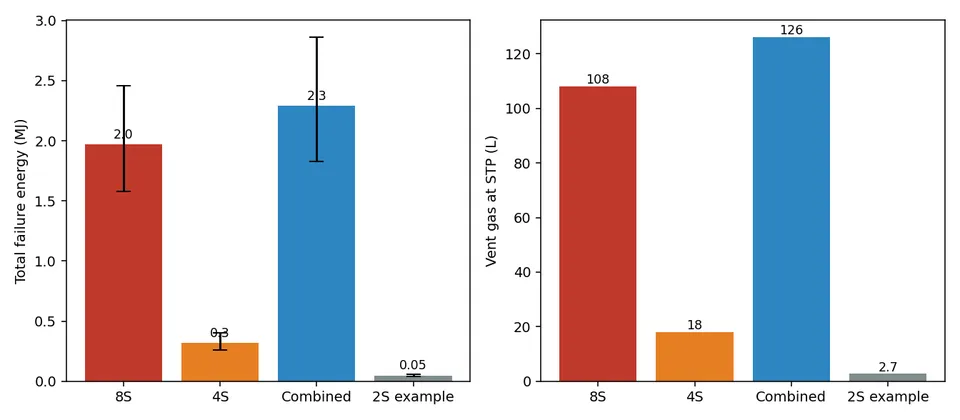
The model evaluated multiple failure scenarios at full charge, including overcharge, external heating, internal short circuit, and over-current events. The predicted failure energy was approximately 1.97 MJ for the propulsion battery and 0.32 MJ for the avionics battery, with the propulsion pack alone producing an estimated 108-144 L of vent gas at standard temperature and pressure. Across the simulated failure modes, peak temperatures reached approximately 1340-1440 degrees Celsius. These results were used to determine the thermal requirements for a battery containment system and evaluate potential mitigation strategies.
Modelled failure & containment
| Parameter | Req. | Result | Unit | Conditions |
|---|---|---|---|---|
| Failure energy, propulsion pack | — | 1.97 | MJ | GNB HV 8S2P 9000 mAh, 274 Wh |
| Failure energy, avionics pack | — | 0.32 | MJ | GNB 4S 3000 mAh, 44 Wh |
| Vent gas volume | — | 108-144 | L | At STP, propulsion pack |
| Peak event temperature | — | 1340-1440 | degrees C | Simulated failure modes, full charge |
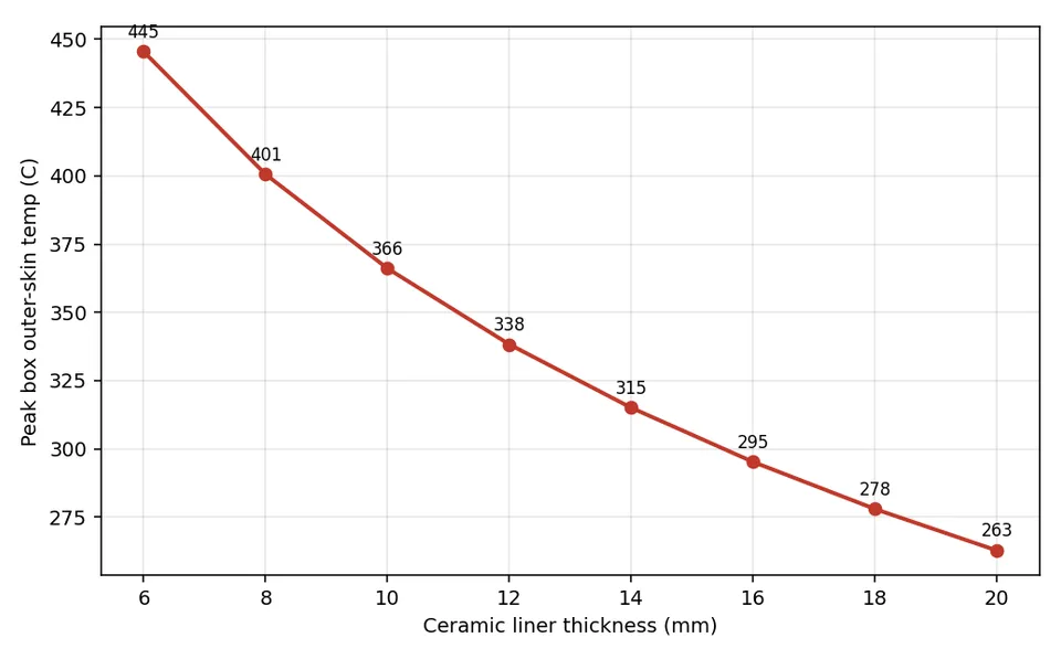
| Inner surface, 13 mm ceramic liner | — | 237 | degrees C | vs approximately 813 degrees C uninsulated fibreglass |
| Outer surface, 13 mm ceramic liner | — | 219 | degrees C | Same case |
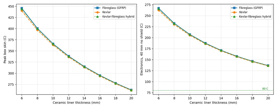
I conducted a material trade study across different composite wall constructions, including fibreglass, Kevlar/aramid, and hybrid layups, alongside thickness comparisons for each. A 13 mm ceramic insulation liner significantly reduced heat transfer into the surrounding structure, limiting the containment box’s inner surface temperature to approximately 237 degrees Celsius and the outer surface to approximately 219 degrees Celsius, compared with approximately 813 degrees Celsius for an equivalent uninsulated fibreglass structure.
One of the most significant findings came as the model was refined. The initial thermal analysis focused primarily on battery behaviour and containment temperatures, but extending it to include the composite wall construction revealed that the limiting factor was not the reinforcing fibre, but the epoxy matrix holding the composite together. While materials such as Kevlar and fibreglass retain structural capability at elevated temperatures, the epoxy matrix softens and degrades at significantly lower temperatures. A higher-temperature epoxy can improve structural margin but does not provide the thermal protection required for a runaway event, since both standard and high-temperature systems eventually degrade at temperatures far below the peak event temperature. This shifted the design focus away from simply selecting stronger composite materials and towards using thermal insulation as the primary protection mechanism.
The model was validated through eight independent checks, including energy and gas conservation, the adiabatic limit, grid convergence, analytical steady-state comparisons, and closed-form pressure calculations. The final analysis was delivered as a reproducible Python modelling pipeline and an interactive spreadsheet calculator, allowing the Structures team to evaluate design changes without rebuilding the model. The resulting data was used to inform the design of a Kevlar battery enclosure and contributed to Huia’s overall battery safety strategy.
The reinforcing fibre looked like the dominant design consideration at first, but the surrounding material system, particularly the epoxy matrix, was what actually controlled the failure behaviour. This finding only showed up once the analysis covered the complete system rather than just the component that seemed most important.
Technologies
Key outcomes
Developed a physics-based thermal runaway model to evaluate lithium battery failure scenarios and guide containment design. The model was validated through eight independent checks and used to size a 13 mm ceramic-lined enclosure, reducing predicted internal temperatures from 813 degrees Celsius for bare fibreglass to approximately 237 degrees Celsius. The analysis identified the epoxy matrix as the primary thermal limitation and was delivered as a reusable Python model and spreadsheet tool for the Structures team.
4.0
Propulsion testing - ESC thermal characterisation
An ESC (electronic speed controller) converts battery power into the rapidly switched electrical current required by an EDF motor. Because the power transistors used for this switching are not perfectly efficient, some of the electrical energy is lost as heat within the ESC itself. In a compact aircraft, this heat generation can become a significant design constraint, particularly when the ESC is enclosed within the airframe with limited airflow.
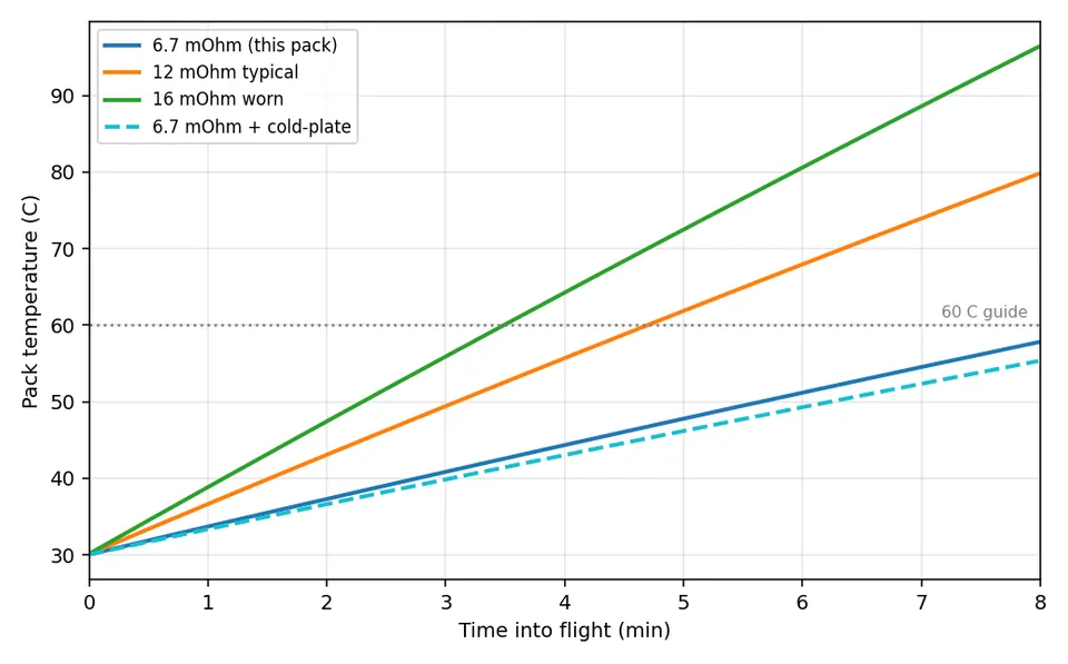
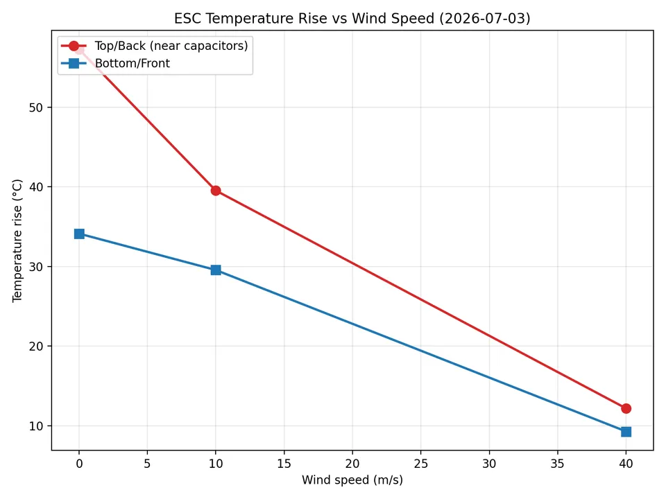
During early Huia development, the ESC operating temperatures were higher than expected, raising concerns about whether the available cooling would be sufficient during flight. The aircraft had limited internal volume and little opportunity for additional active cooling, making it important to understand the actual thermal behaviour before adding unnecessary complexity. Testing showed that the key limitation was not peak temperature during short operation, but the rate at which heat accumulated. Increasing the ESC’s thermal mass reduced the rate of temperature rise, and because Huia’s flight duration was short enough that the ESC would not reach steady-state temperature, additional active cooling was not required.
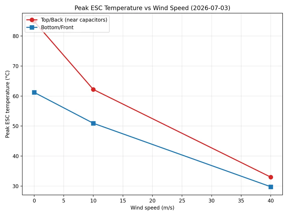
To validate the thermal performance under realistic conditions, I instrumented an ESC with two thermocouple pairs positioned near the upper rear section of the board and the lower front section. The ESC was then tested under load at airflow conditions of 0, 10, and 40 m/s in the wind tunnel using the automated test controller developed for hardware characterisation. The same throttle-ramping and dual-CSV logging pipeline was used to ensure repeatable measurements. An initial test campaign identified uncertainty in one dataset, so the complete characterisation was repeated, with the retest used as the final dataset.
The results showed a significant reduction in ESC temperature with increasing airflow. The upper sensor reached approximately 85 degrees Celsius under static conditions, reducing to 62 degrees Celsius at 10 m/s and 33 degrees Celsius at 40 m/s under load. The lower sensor remained cooler at low airflow, measuring approximately 61 degrees Celsius static, but the temperature difference reduced as airflow increased, converging within a few degrees at 40 m/s. Some raw measurements show an initial temperature decrease due to incomplete cooldown between consecutive runs, which was expected from the test sequence and accounted for during analysis.
This testing demonstrated that passive thermal management was sufficient for Huia’s operating profile, avoiding unnecessary additions to the cooling system. The wind-tunnel data settled it: a worst-case theoretical estimate would have pushed the design toward active cooling the flights never needed.
Technologies
Key outcomes
Designed and executed wind tunnel testing to characterise ESC thermal performance under realistic airflow conditions. Instrumentation across the ESC showed peak temperatures reducing from approximately 85 degrees Celsius at static conditions to 33 degrees Celsius at 40 m/s airflow. The results showed that temperature rise was dominated by transient heating rather than steady-state operation, supporting a passive cooling approach for Huia’s short-duration flights.
5.0
Launch system - electrical control & release
Due to the amount of energy stored in the rail launcher’s spear-gun rubber propulsion, capable of accelerating payloads of up to 10 kg to 60 m/s, the control and release system needed to be remotely operable and reliable by design. I led the development of the electrical control system for the group’s 5 m rail launcher, with the ability to handle peak currents approaching 200 A.
Managing this level of current was one of the primary engineering challenges. The system required careful consideration of power delivery, switching hardware, protection, and cable sizing to ensure reliable operation under high-current loads. Rather than relying on standard RC electronics, the design was built around an automotive battery and dedicated high-current switching hardware, providing a robust and field-deployable system capable of repeated launcher operation.
The system provides remote operation of the launcher winch, allowing tensioning and preparation to be performed from approximately 20 m away while keeping operators clear of the launch mechanism. The electrical design incorporates power isolation and over-current protection throughout the high-power path to improve reliability and protect both the equipment and operators during operation.
The completed system provided a portable and reliable launcher control solution. The project demonstrated the challenges of designing practical control electronics for high-current electromechanical systems, where power delivery, reliability, and safe operation must be considered together.
Technologies
Key outcomes
Designed and built the electrical control system for UC Aerospace’s 5 m rail launcher, supporting remote operation of a high-current electromechanical system. The design operated from a field battery supply, handled peak currents approaching 200 A, and incorporated power isolation, fusing, and over-current protection.