- Role
- Electrical systems lead — PCB layout, RF front-end and firmware integration
- Timeframe
- 2025
Alerts on a high-power rocketry range have to carry between the launch site and personnel spread across it, and arrive dependably and with low latency; they are what maintains safety compliance and coordinates launch activities. As part of the Third-Year Electrical Engineering Design Course, I collaborated with a team to develop a LoRa-based launch range warning system for that link.
Within the team I led the electrical design and implementation, managing the PCB layout, RF front-end development, and firmware integration. The system was built around the NUCLEO-WL55JC development board, selected for its STM32WL dual-core microcontroller with an integrated LoRa transceiver, which gives long-range communication capability in a compact, efficient platform. I implemented the LoRa communication stack within a C-based operating system and configured it for half-duplex operation, enabling reliable bidirectional data exchange between the launch site and the range safety stations.
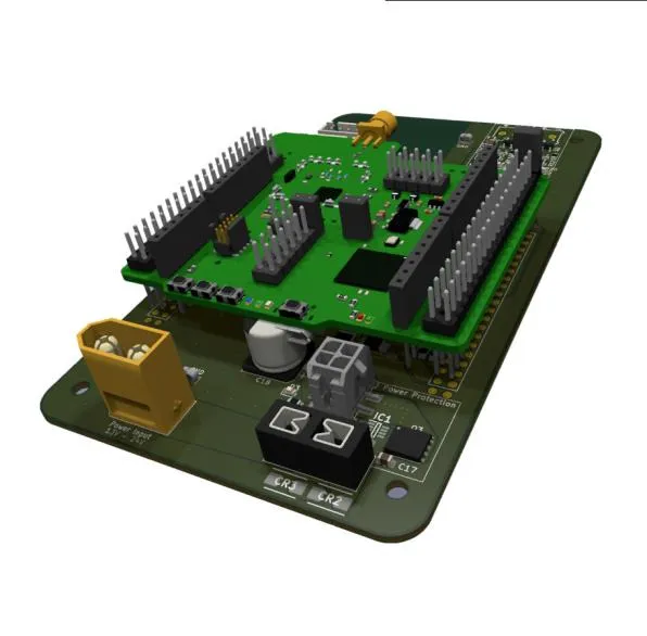
The custom PCB houses and interfaces with the NUCLEO-WL55JC, integrating peripheral circuitry for power management, RF connectivity, and system protection. The supply is a switching regulator-based design capable of handling inputs up to 8S LiPo (33.6 V) and generating regulated 12 V and 5 V rails. Power protection uses ideal diode controllers for reverse polarity, along with overvoltage and undervoltage protection to safeguard all onboard electronics. The board also carries integrated siren and beacon switching, and temperature and humidity logging.
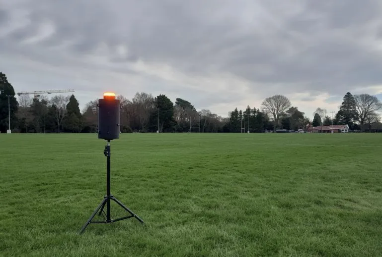
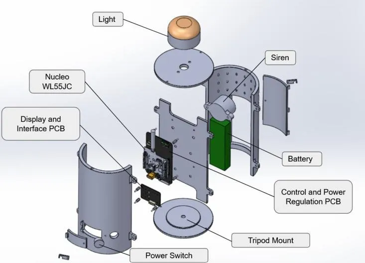
The unit is built around a central chassis plate. The control and power regulation PCB mounts to it with the NUCLEO-WL55JC beside it, and the siren and battery sit against the same plate. The display and interface PCB and the power switch go on the front shell, the light dome closes the top and a tripod mount closes the base.
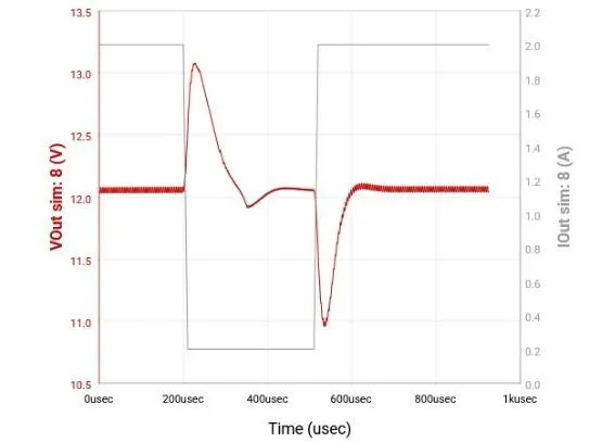
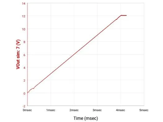
Throughout schematic and hardware development I ran transient load simulations, startup behaviour simulations, and electrical performance analysis to validate regulator response, inrush current limits, and voltage rail stability under dynamic conditions. The target was reliable performance during rapid power transitions and operational stress scenarios.
Technologies
Key outcomes
Designed and implemented a LoRa-based range warning system capable of reliable long-distance operation and stable power delivery under load. The system demonstrated consistent LoRa communication, effective hardware protection, and a scalable power architecture, fulfilling all course design and testing requirements.