- Role
- Avionics and Tracking Lead — controller subsystem: schematic design, circuit modelling, hardware validation and enclosure CAD
- Timeframe
- 2024-2025
UC Aerospace’s rocketry operations needed one launch interface that would serve both high-powered and low-powered rockets and remain safe, wireless and fault-tolerant in the field. The system ran on lithium-ion batteries and was composed of two major components: a launch controller and a launch hardware unit at the pad. I led the design and development of the controller subsystem, while a team member focused on the launch pad hardware.
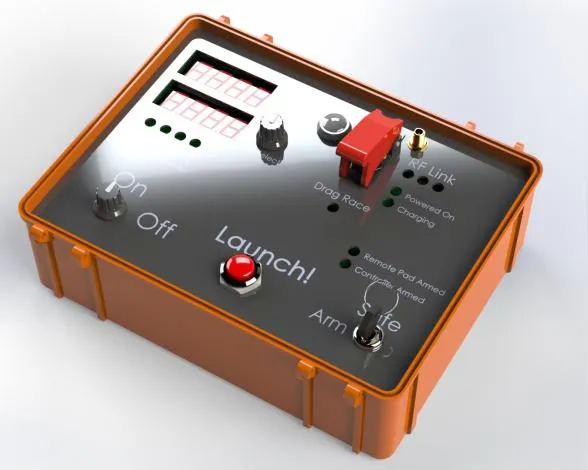
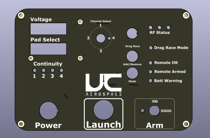
The controller was powered by dual 18650 lithium-ion cells with integrated USB-C charging circuitry, giving portable and reliable operation with charging on the board rather than off it. Its user interface consisted of two seven-segment displays, status indicators, and a launch button.
The button interface was debounced in hardware rather than in firmware, using RC filters and Schmitt triggers. A mechanical contact chatters as it closes, so an input reading it directly sees several edges where the operator pressed once. The RC network filtered that transient and the Schmitt trigger’s hysteresis resolved what remained into a single clean transition, so the signal arriving at the digital input was already unambiguous rather than something firmware had to interpret. The requirement was clean, reliable digital input even under the noisy electrical conditions of a launch site.
The two units communicated wirelessly using the LoRa protocol, which gave long-range, low-latency communication between the controller and the launch pad hardware. The intent was high reliability even in electromagnetically noisy or distant launch environments.
Beyond the electronics, I modelled and designed the controller enclosure and mounting hardware using 3D CAD tools, so the PCB and external components would integrate cleanly into the finished unit. I was also responsible for PCB schematic design, circuit modelling, and hardware validation of the controller board.
Technologies
Key outcomes
Delivered a portable, battery-powered launch controller with long-range LoRa communication to the pad hardware, debounced input reliable under electrically noisy launch conditions, and a custom enclosure integrating the PCB and external components into one field-ready unit.