- Role
- Avionics Team Lead — programme coordination, learning materials, example PCB projects and schematic templates
- Timeframe
- 2024
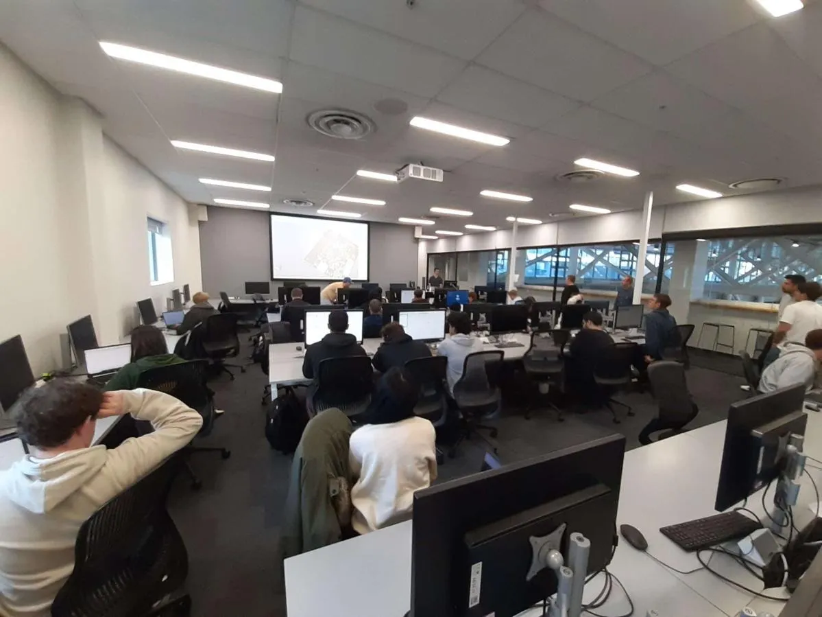
I organised and led a series of five hands-on electronics tutorials for UC Aerospace members, introducing the fundamentals of embedded systems and flight computer design. The participants had little prior electronics experience, so the series started at datasheets and component packages and ended with the participants who completed the series assembling and testing their own SMD flight computer.
In this role I was responsible for coordinating the tutorial programme, developing learning materials, and designing the supporting resources, presentations, example PCB projects, and schematic templates — used throughout the workshop series to guide participants through the practical design process.
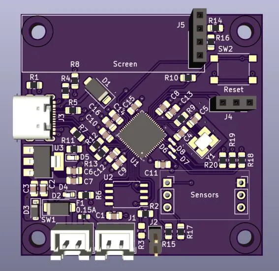
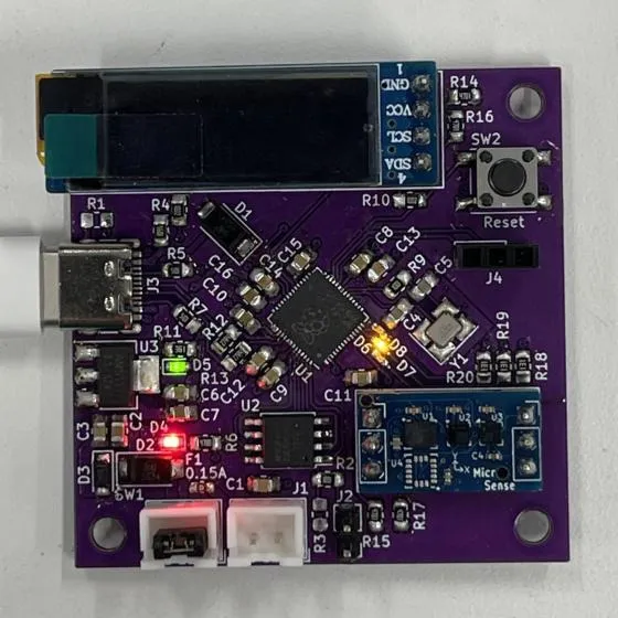
The programme consisted of five structured workshops, each focusing on a core area of avionics and electronics design:
- Component Fundamentals: Understanding datasheets, comparing component packages, and sourcing components through electronic retailers.
- Flight Computer Architecture: Exploring major subsystems including power regulation, reverse polarity protection, overcurrent, and overvoltage protection.
- Sensor Overview: Examining the functions and purposes of key sensors such as the magnetometer, 6-axis IMU, and barometer, as well as discussions on decoupling capacitors, signal routing, and power planes.
- Schematic Design Workshop: Teaching best practices for schematic layout, documentation clarity, and hierarchical organisation for complex projects.
- PCB Layout Workshop: Introducing routing strategies, trace sizing for different current levels, and design principles for a simple data-logging flight computer PCB.
Participants who completed all sessions had the opportunity to assemble and test their own SMD-based flight computers, gaining hands-on experience in both design and practical electronics assembly.
Technologies
Key outcomes
Led a five-part hands-on electronics tutorial series, developing learning resources including presentations, example PCBs, and schematic templates. Guided participants through component selection, flight computer architecture, sensor integration, schematic best practices, and PCB layout. Participants successfully designed, assembled, and tested their own SMD-based flight computers, gaining practical experience in both design and electronics assembly.